Motivation
I am living in a downtown apartment where an outdoor “large” antenna is impractical. My only feasible location for a fixed antenna is at the balcony. Obviously for SWL-ing at frequency below ~15MHz, only electrically small 1 antennas can be used. Moreover man-made noise is very high in my area, rendering a whip antenna unusable.
An active loop antenna is a viable solution. Loop antennas, like ferrite-rod antennas, pick up magnetic fields and theoretically do not response to electric fields which are the major sources of noise in urban area. My space dictates using a electrically small loop with a maximum feasible diameter of about 1m. Such a small loop will perform very poorly on its own for frequency below 20MHz. Adding a low-noise amplifier to boost the weak signal picked up by the loop can make performance comparable to a “big” antenna.
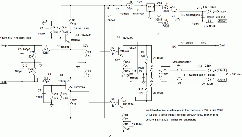
After browsing the web, I found the design by Chavdar Levkov LZ1AQ quite promising. Based on LZ1AQ’s circuit (fig.1), I make some mods to fit my usage environment.
Circuit Description
LZ1AQ gives highly detailed descriptions on the schematics (fig.1) and antenna design matters. Please visit his site on the following link: https://www.lz1aq.signacor.com/docs/wsml/wideband-active-sm-loop-antenna.htm
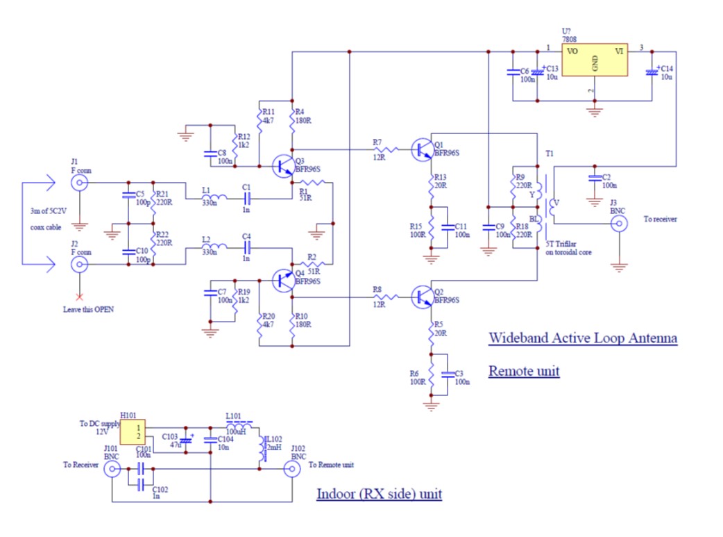
Here I only describe the mods I have made. Refer to fig.2.
- I change all the transistors to BFR96S which has a fT of 5GHz for wider frequency coverage.
- As the BFR96S has lower current and power rating than the PN2222A in the original design, I reduce the supply voltage to 8V by changing the DC regulator to a 7808.
- The “loop” is made from a 3m segment of 5C2V coax cable. One end of the shield is grounded to increase immunity to interference from electric fields.
- The output is fed via J3 and coaxial cable to the receiver. This node also serves to obtain power from the indoor unit via the feed cable. C2, C14 provide decoupling.
- Refer to Fig.2, power is fed to the active loop from the “Indoor (RX side) unit” which consists of choke coils L101, L102 and decoupling capacitors C103, C104.
Note on Construction
This is an easy-to-build circuit that needs no tuning. Breadboarding is totally acceptable as long as component lead length are kept to minimum, and a ground-plane is used. Refer to fig.3. Attach a copper foil to one side of a breadboard to create a ground plane. The opposite side is for mounting most of the components. A ground connection can be created by soldering a short length of wire through a hole on the board. One end of this wire is soldered to a component connection; the other end to the ground plane. SMDs (surface-mounted devices) are highly preferable to leaded ones. A breadboard with 2.54mm (0.1 in.) pitch is handy for mounting SMD L/C/R of size larger than 0603 and SOT-23 transistors. Leaded components are fully acceptable also, as in LZ1AQ’s original build.
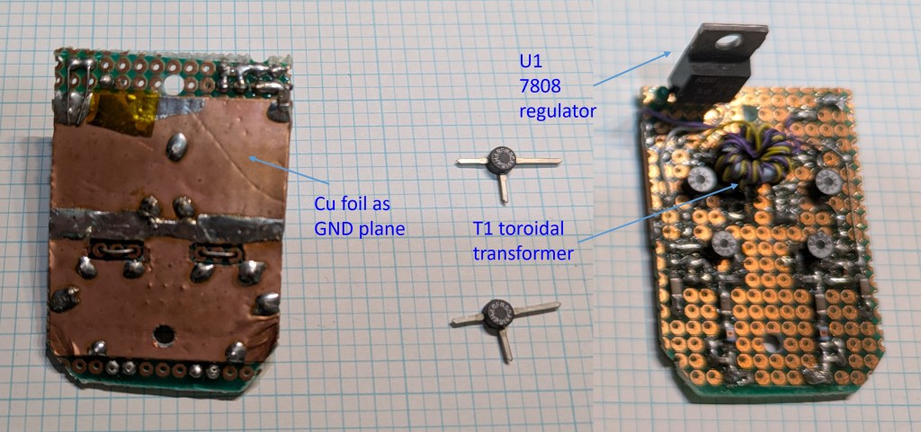
T1 is made up of 5 trifilar turns windings on a toroidal core which material meets the working frequency range. Construction begins by cutting 3 wire segments of sufficient length for all the turns plus allowance for leads. It is preferable to use different color for each wire. I use #30 yellow, black, purple wire-wrap-wire . Thickness of wire is not important.
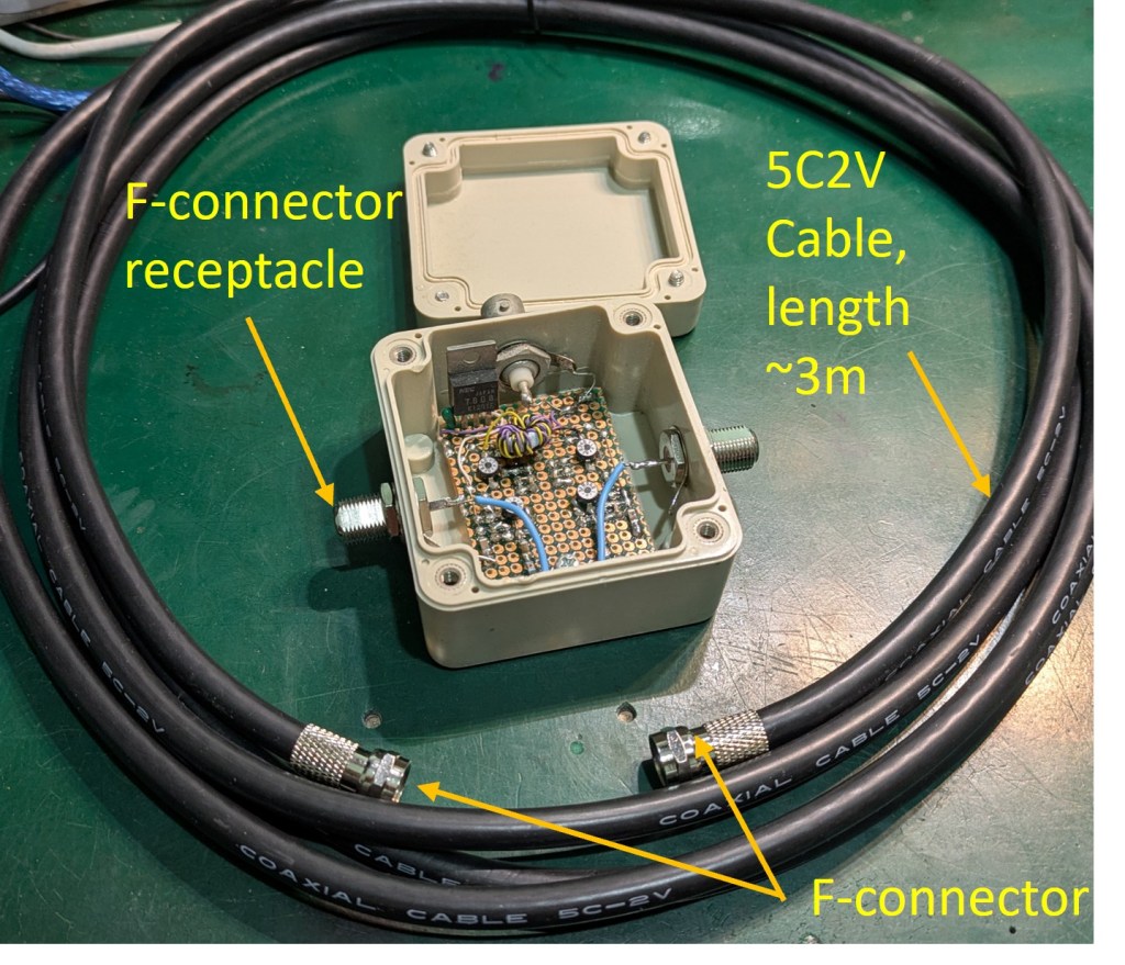
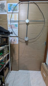
The circuitry is housed inside a robust plastic box which hopefully can protect the components from semi-outdoor environment. The loop is made up of 3m of 5C2V cable which is attached to the box via 2 F-connector, resulting in a loop diameter of roughly 1m. A F-connector and the 5C2V cable, which is mostly used in A/V products, has a characteristic impedance (Z0) of 75 Ohm. In our application Z0 is not important, as each end of the loop faces the emitter of a common-base stage which has very low impedance. The 5C2V coax is handy as it is available in 3m length with F-connectors attached to both ends. (See fig.4.) Simply mate the F-connectors with the F-receptacles on the box. Important: Only one of the F-receptacle must be grounded; leave the other floating2.
Fig.5 is the completed antenna. It is small enough to be housed inside my clamped working space. Construction is not critical. You can use whatever means to hold the circular loop to shape.
Performance Test
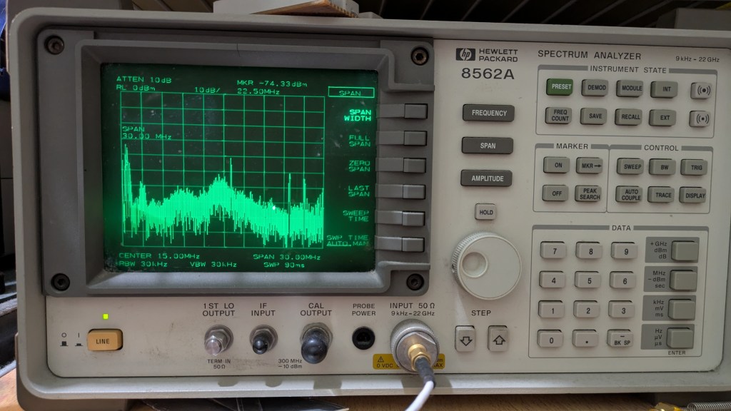
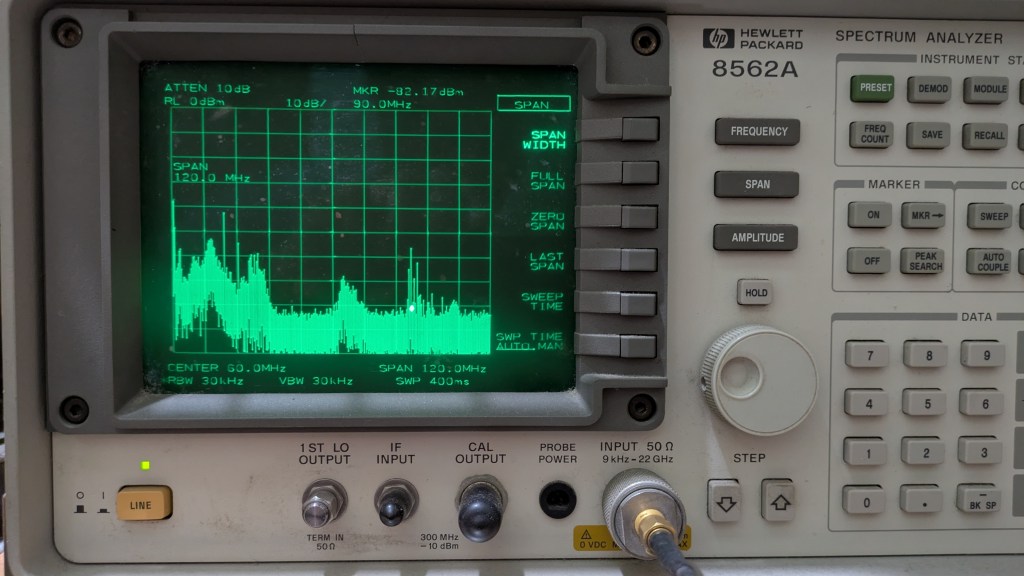
I connected the Active Loop output to a spectrum analyzer. For a span of 30MHz, many signals could be picked up (see fig.6). While this antenna is primarily aimed for MW/SW reception, it can also cover the FM broadcast band 88~108MHz (see fig.7). This is somewhat a nice surprise as the material for T1 toroid causes frequency response to roll off at about 40MHz. I think the high fT and low noise of the BFR96S transistors are the key.
Listening test confirms the effectiveness of this Wideband Active Loop. With the loop mounted indoor (fig.5) and connected to a “RTL-SDR V4” receiver, MW broadcast can be received with high SNR and minimal interference. A few SW stations can be received during daytime. Even FM broadcast can be received with high SNR. Such performance is not possible with a whip, at the same location.
Further work
I am going to mount the Loop in my balcony. Since a loop is a directional antenna, I need to find an optimum orientation. A more aggressive approach is to mount the Loop on a platform which can be remotely rotated.

Leave a comment