Several months ago I fixed the video offset problem of my HP8562A. (See the post: HP8562A Spectrum Analyzer Repair: Fixing Video Offset / Display Issues. ) Last week my Tek 494P refused to work – the display was blank after power on. A quick diagnosis revealed the following:
- The power supply unit (PSU) is good, as the LED indicators show up normally.
- The MCU and various control circuits are good, as key inputs can be recognized. Moreover I can hear relay switching sound when I change some setting, for instance, attenuation.
Troubleshooting
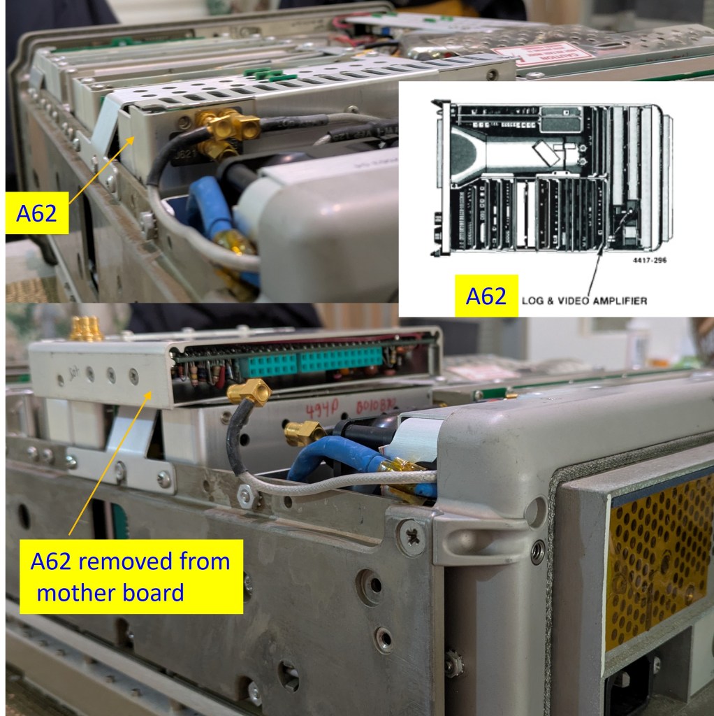
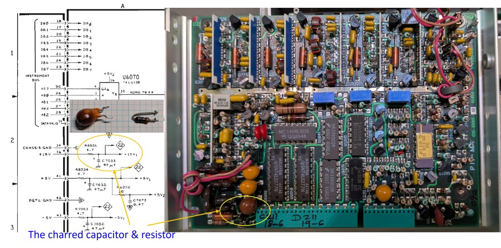
I remove the instrument cover to do visual check (fig.1). I power it on again. Naturally the first step is to check the various DC supply voltages to confirm if they are within spec. Interestingly when I am probing the test points one by one, I smell something strange. I turn off the equipment immediately and search for the source of unpleasant smell. The log & Video Amplifier module (A62) seems to be the culprit. Further disassembly work confirms this assumption. Refer to the fig. 2, the problem is a shorted tantalum capacitor. A resistor is also burned. Consulting the service manual, I find that the capacitor in question is C7033 which is the +15V supply decoupling capacitor. It is evident that this capacitor somehow becomes a short circuit so that R8031 (4.7ohm) drops most of the supply voltage. As a result the associated circuits do not receive 15V supply and thus malfunction.
Fixing it
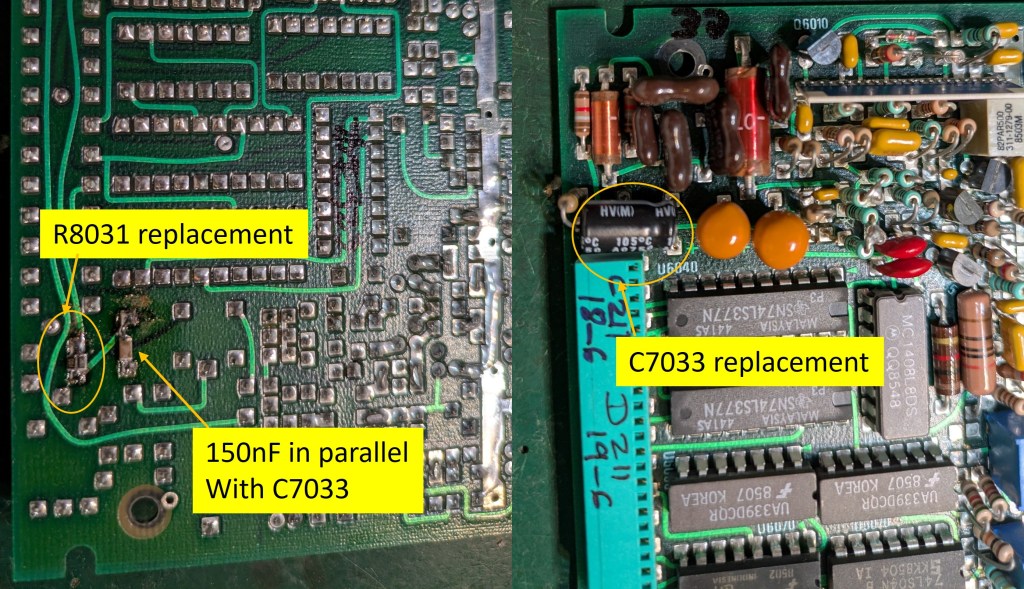
Repair work is not difficult but I do not have the tantalum capacitor for exact replacement. As a quick or perhaps temporary solution, I replace the 47uF 20V tan cap with a 100uF 25V electrolytic cap. I connect a 150nF 50V X7R SMD ceramic cap in parallel with it to improve high frequency decoupling. The charred 4.7ohm resistor is replaced with two 1206 10ohm resistors in parallel to ensure sufficient wattage. See fig.3.
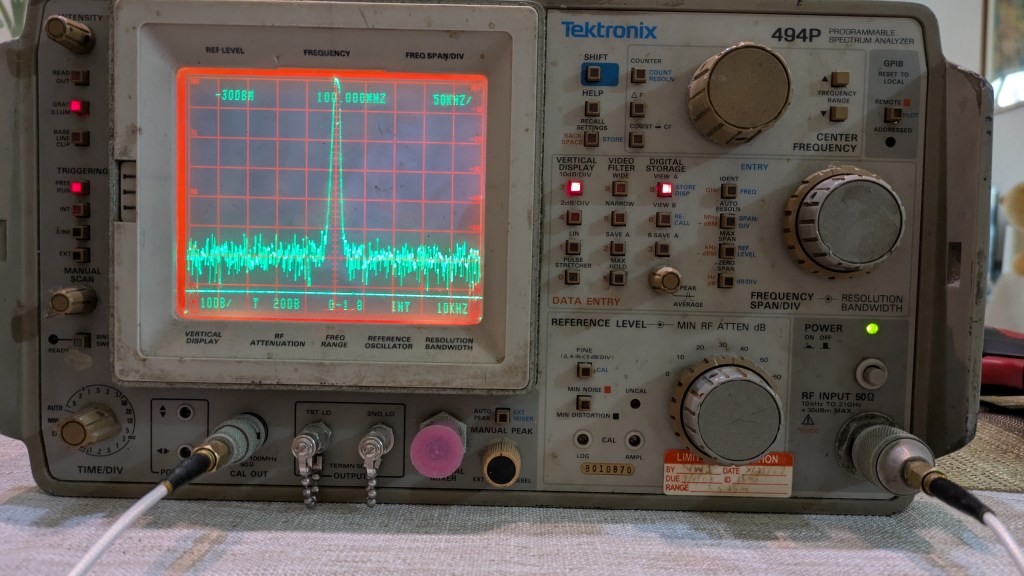
After the above fixes the set is back to normal. See Fig.4.
After thoughts
Tantalum capacitors are notorious in their zero tolerance to over voltage. Actually a derating factor of 50% must be allowed; some companies even require 70%. For example, if the maximum withstanding voltage is 15V, the working voltage (WV) of the tan cap must be 15V * 1.5 = 22.5V for 50% derating. This is a reliability precaution. For the Tek 494P the tantalum capacitors for the +/-15V rails have a WV of 20V. This is clearly a compromise and the reason is size — diameter and headroom. The 494P was then a top-of-the-line instrument. It was not a cost concern to use smaller and less expensive capacitors. It was the size that dictated the use of smaller capacitors with lower voltage rating. It is obvious from the photos that there is no more room for a larger capacitor.

Leave a comment