The Problem
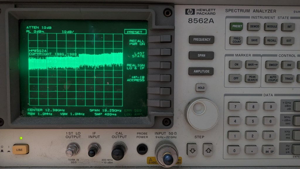
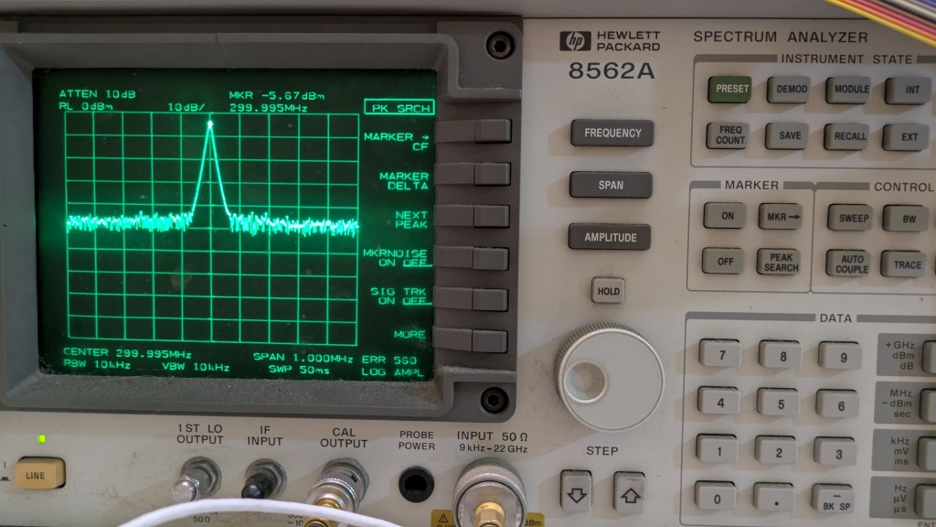
My HP8562A has been in excellent condition for many years until one day when I powered it up, the displayed trace was weird. The whole spectrum display was shifted up, as shown in Fig.1. Trying to display the built-in cal. signal further confirmed the problem. The photo below showed the 300MHz cal. signal, which level was incorrect, and the whole trace shifted up. On the lower right corner of the display, error message “ERR 560 LOG AMPL” appeared. (Fig.2)
Troubleshooting
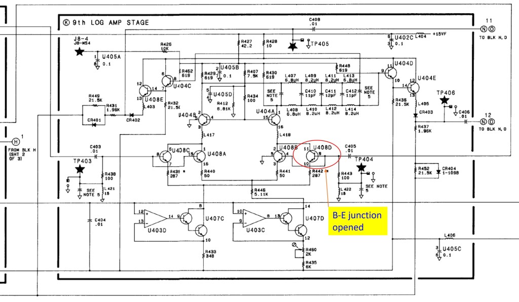
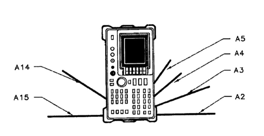
The service manual suggested that the problem was with the Log Amp in the A4 assembly. I did some painstaking checks on the DC levels at various test points to find out that U408 was the culprit. This chip is a transistor array which in this design constitutes part of the 9th stage Log Amp. Actually the problem was an opened Q408B as indicated in the schematics (Fig.3). Fig.4 below shows the location of the A4 assembly. Fig 5 shows the disassembled A4 with the faulty chip removed (lower right corner).
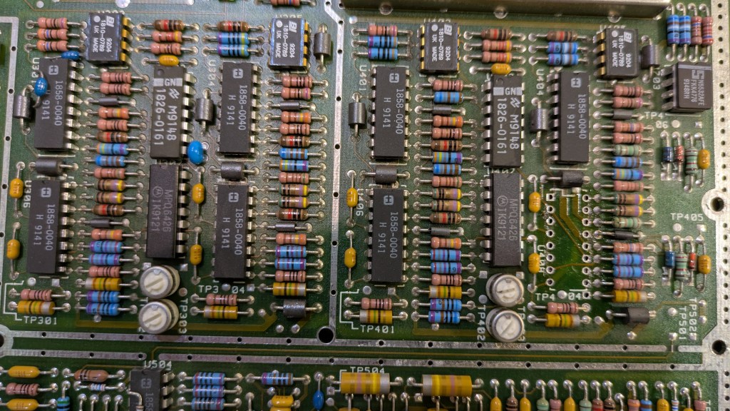
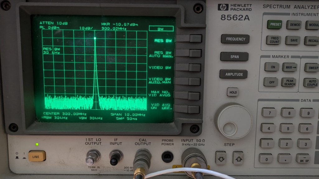
The chip was marked with a HP proprietary number, but the part list indicated a CA3127E, which was a transistor array by RCA. This chip (and RCA) has been obsolete for a long time. Fortunately it is still available at eBay in small quantity with a “reasonable” price. I ordered a few pieces and had the damaged chip replaced. My HP8562A is now back to normal. See Fig.6 below.
Remarks
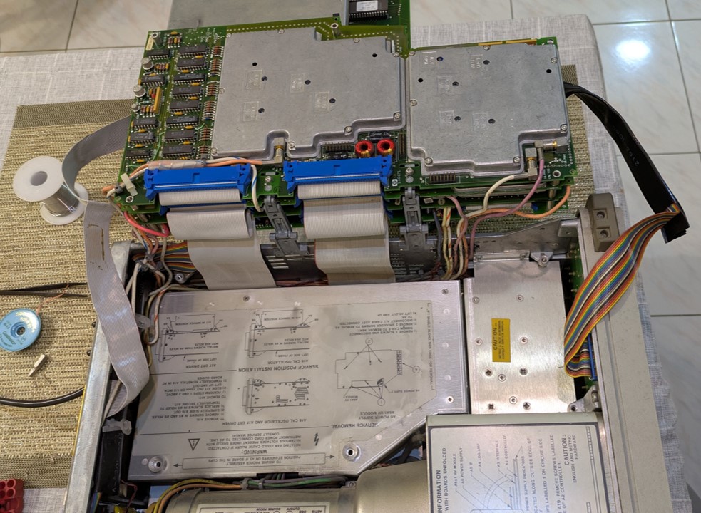
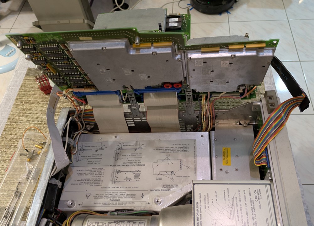
The HP8562A is relatively straight forward to disassemble. However you should study the figures in the service manual carefully before working on the assemblies. Several “long” screws with different length must be removed before the assemblies can be unfolded. Note their locations. During reassembling pay attention to use the screws with proper length on their designated locations. Avoid stressing the connecting coax and/or ribbon cables when you unfold the assemblies. Refer to Fig.7 and Fig.8.
Another precaution: Do not adjust the trim pots!
Updates
29th April 2026: Add partial schematics of the A4 Assembly. Add more remarks.
 From Hobby to Professional
Leave a comment