Introduction
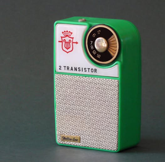
In the mid 1950s, while almost all table-top radios used vacuum tubes, pocket-size transistor radios started to appear. Most of these radios employed the superheterodyne architecture which needed at least 4 transistors for adequate performance. However transistors at that time were very expensive. For cost saving, a few low-end models used the tuned radio frequency (TRF) architecture instead of superheterodyne to save transistors. Performance was marginal, but still usable for local and strong stations, and, most important, these radios had a much lower price tag. Perhaps the most ingenious TRF design was the reflex circuit in which a single transistor amplified both RF and AF signal. A 2-transistor reflex circuit had sufficient gain to drive a loudspeaker. At that time quite many commercial models using reflex circuit were available. Fig.1 shows the Boy’s Radio which was available in U.S. market in the early 60s. Interestingly, in the old days manufacturers were generous to attach the schematic circuit inside the cabinet of a radio. This was very handy for the service technicians as well as for the hobbyists who could copy the circuit to build their radios. As transistors gradually became cheaper from the 60s onward, superheterodyne circuits were employed exclusively. Reflex circuit was however popular among hobbyists up to the mid-70 as they were easy to build and need no alignment (almost). I remember back in the early 70s I have built a reflex radio which circuit is very similar to the Boy’s Radio.
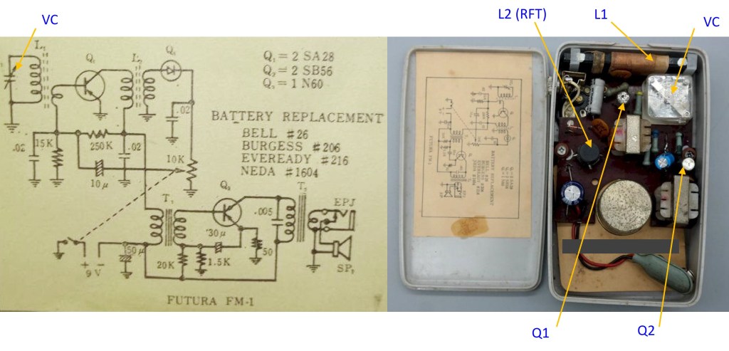
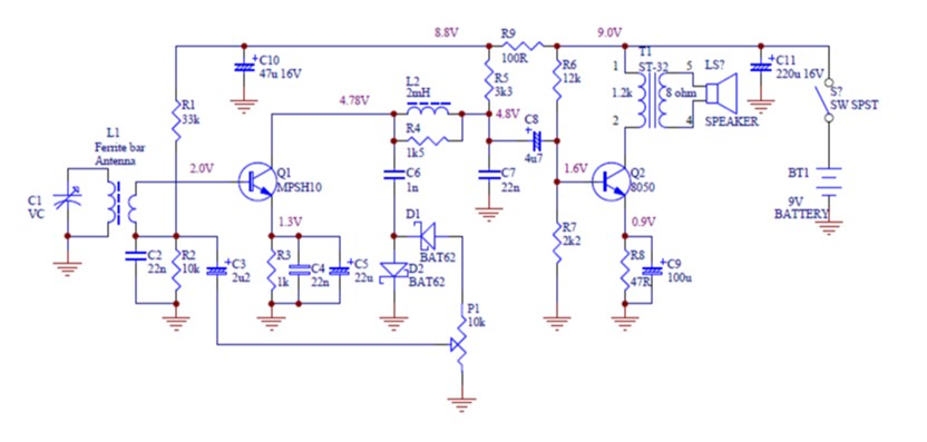
In this article I will describe a 2-transistor reflex circuit that is adapted for using off-the-shelf components of the present day. Comparing the schematics in fig.1 and fig.2, we can notice that the antiquated PNP germanium transistors are replaced with modern NPN silicon types. The hard-to-find RF transformer (L2/RFT) is replaced with a choke coil; germanium diodes are replaced with Schottky diodes. Detailed circuit description is as follows.
Circuit Description
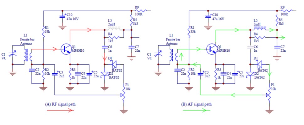
To understand how the reflex circuit works, please refer to fig.3. The RF signal picked up by the ferrite-bar antenna is amplified by Q1. L2 is a RFC (radio frequency choke) which presents a high reactance to RF signals while passing DC and audio. C7 has very low reactance to RF signals. Therefore Q1 sees a load impedance which is the parallel of L2, R4 and the impedance of D1 and D2 via C6. R4 provides damping to L2 to prevent oscillation. D1 and D2 form a voltage-doubling detector to extract the envelop of the AM signal from the collector of Q1 via C6. Volume control is by means of P1 which routes the recovered audio signal back to the base of Q1 via C3 (see the green paths). Note that the secondary winding of L1 has very little impedance to audio signal. The load of Q1 as an audio amplifier is R5, as L2 has negligible impedance to audio signals while C7 has very high impedance. C6 has very high impedance to audio signal and so the amplified audio will not be looped back and cause instability. The boosted audio is routed via C8 to Q2 which is a single-end class A PA (see fig.1). The current configuration gives a maximum output of about 50mW.
Construction and Testing
This simple circuit is easy to construct. Bread-boarding is totally acceptable. I use the “dead-bug” approach (see fig.4). As I intend to test the “reflex action” only, I do not build the audio part. I connect the audio output from Q1 to an active speaker box for listening test.
I hereby provide some hints on obtaining the (relatively) hard-to-find components for those who want to build the complete radio.
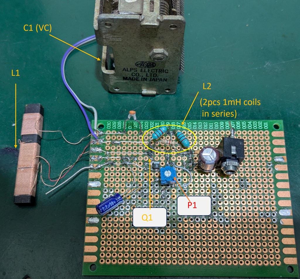
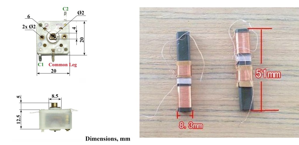
In the original circuit, C1 is a single variable capacitor (VC) which has been obsolete for a long time. The alternative is to use a 2-gang VC, which is still available in some component stores and eBay. Fig.5a is an example of such a 2-gang VC that can be used in this circuit. These miniature 2-gang VCs were used in all pocket radios that employed superheterodyne architecture in the 60s to 80s, before PLL synthesized digital-tuning radios became popular. They had thin PVC foils as dielectric and hence had size much smaller than air dielectric VCs. Note that in a superheterodyne radio, one gang is for antenna tuning while the other gang is for local oscillator tuning. Some of these 2-gang VCs has unequal capacitance, with the “antenna gang” having larger capacitance. Usually there are markings on the plastic housing to avoid ambiguity; “A” indicates antenna, “O” indicates oscillator. For our application we have to use the “antenna gang” only. Just leave the “oscillator gang” unconnected. The “antenna gang” of a VC for use in pocket radios usually has a capacitance of 4~240pF; a few have higher maximum capacitance up to 300pF. This can cover the AM broadcast band with a small ferrite-bar antenna (coil) with an inductance of about 360uH (Fig. 5b). I will provide details on calculation of inductance and capacitance for antenna and local oscillator circuits in the superheterodyne receiver topic which appears later in this series.
Diodes D1 and D2 should be point-contact germanium types (such as 1N34, 1N60, SD46, OC71) for best result. Unfortunately Ge diodes are hard to find nowadays. The best compromise are small-signal Schottky diodes such as BAT62. Silicon diodes such as 1N4148 are poor choice, as their high turn-on voltage (~0.7V) worsens sensitivity significantly.
After soldering work is done, connect a 9.0V DC regulated power supply to replace the 9V battery. Check the DC voltage at the various points as in fig.1. Voltages within +/-10% of the indicated values are acceptable. If all DC conditions are met, relatively strong local radio stations may be tuned in by rotating variable capacitor C1. As the ferrite-bar antenna is highly directional, it may be necessary to alter its orientation for best reception.
The ferrite-bar antenna (L1) must be separated from the RFC (L2) for at least 3~4cm (~1.5″) to prevent oscillation due to feedback of RF signal.
Alignment
Alignment for a TRF radio is very simple. We only need to ensure the whole broadcast band can be tuned to. In other words, the lowest frequency (520kHz) can be received by turning variable capacitor (C1) for maximum capacitance; the highest frequency (1750kHz) can be received by setting C1 for minimum capacitance.
Procedures
Refer to fig.6.
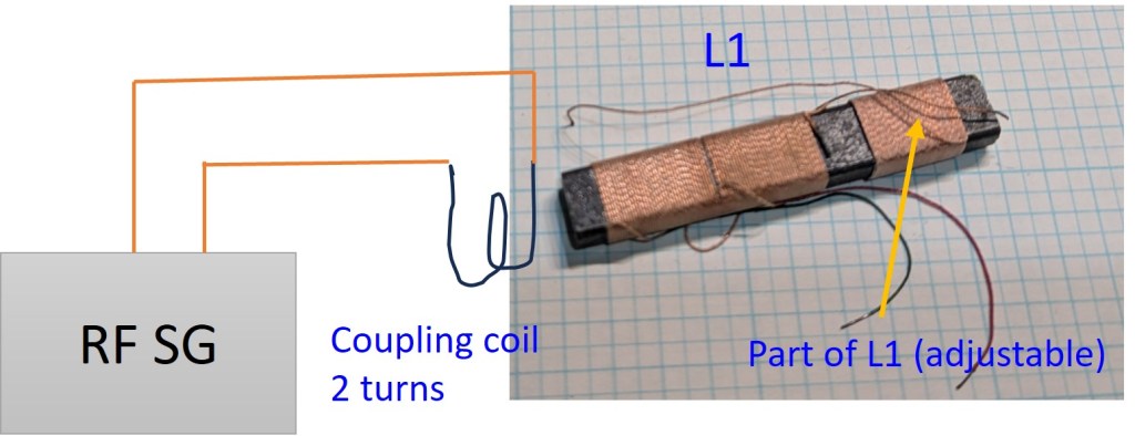
- Set the RF Signal Generator to f = 520kHz, modulation = AM 30%, output level = -47dBm.
- Connect the SG output to a 2-turn loop which diameter is just sufficient to wrap around L1 (ferrite-bar antenna).
- Set variable capacitor C1 for maximum capacitance.
- Slide the adjustable part of L1 to obtain maximum audio output.
- Change the RF SG frequency to 1750kHz.
- Slowly reduce the capacitance of C1 until maximum audio output is obtained. This should take place when C1 is close to its minimum capacitance position.
- Apply some glue or wax to secure the position of the adjustable part of L1.
Afterthoughts
Listening test reveals the shortcomings of this simple circuit:
- The difference in volume level among strong local stations and weaker distant stations are very obvious, due to lack of automatic gain control (AGC).
- Relatively closely located stations are mixed up due to insufficient selectivity.
In the coming posts I will discuss the Superheterodyne principle which results in performance much better than tuned-radio-frequency (TRF).

Leave a comment