The Problem
My AR3000 has been in occasional use for 30+ years. Several months ago it failed to start. Pushing the power button resulted in no sound and the icon “PLL ERR” showed up in the LCD screen.
Diagnosis and Repair
I had the gut feeling that the problem was due to faulty electrolytic capacitors. It turned out that I was right. The culprit was not difficult to locate but the procedures were tedious. This is due to the complex circuitry and the package method.
If the PLL circuitry is suspected, the first step in diagnosis is to check the synthesizer/PLL circuitry which for the AR3000 is located in a dedicated PCB. The steps taken to access it is quite involved, however. Below are the troubleshooting procedures I use:
- Remove the top and bottom plastic covers by unscrewing several screws which locations are obvious.
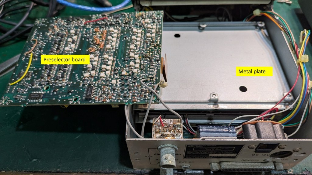
- With the set faced up, remove the 6 screws that fasten the preselector board. Disconnect all the connectors on one side of the board. Flip the board over and let it sit on one side of the set. See fig.1.
- Remove the 4 screws (2 on each side of the side) that fasten the metal plate. Remove the metal plate to expose the PLL board (fig.2).
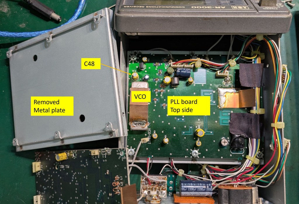
- Remove the 6 screws that fasten the PLL board and flip it (fig.3).
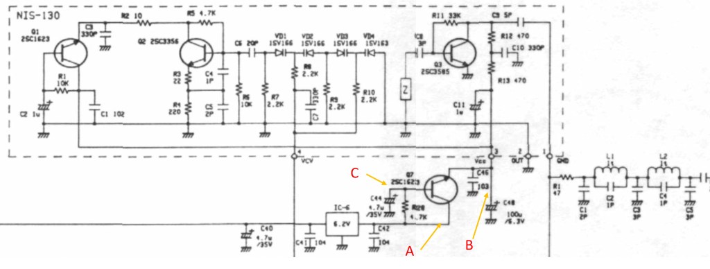
- Now the various test points on the PLL board are accessible. Turn the set on. With a DVM, check the supply to the VCO. Refer to the partial schematic (fig.4), DC voltage at point A should be 6.2V +/-0.1V, point B should be 5.2V +/-0.1V. In my case, point A is 6.15V but point B is at zero volt (0V).
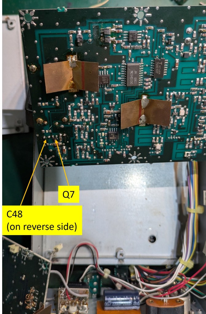
- Check the DC voltage at point C. Normally it should be at 5.9V +/-0.1V. However in my case point C is at about 6.15V, almost same as that at point A. This implies that transistor Q7 is faulty. Checking it with the “diode range” of a DMM confirms that Q7 is damaged — emitter open circuit.
- Turn off the set. Measure the resistance from point B to ground. It should be very high. However in my case resistance is just a few ohms. This implies C48 (100uF 6.3V) is short-circuited.
- Replace Q7 and C48. Turn on the set and check the voltages at points A, B, C again. The values should be then back to normal.
- Check the DC supply voltages to various circuit blocks, for instance, PLL chip, loop-filter op-amp, for normal value.
- If no other circuit block is defective, reassemble the set by reversing procedures 2 to 4.
- Turn on power. The PLL ERR icon disappears and the set resumes normal function.
Conclusion
In this case, the “PLL error” is due to no power supply for the VCO. The root cause is a short-circuited electrolytic capacitor which in turns destroys the transistor which supply power to the VCO. There are many other circuit sections that may result in PLL error if any one of them malfunctions. Most of the times, we may need to painstakingly check the DC and/or RF signals at various test points.
I was fortunate to check the VCO supply first and hence quickly located the culprit.
Have you come across similar issue or other problems with your AR3000?

Leave a comment