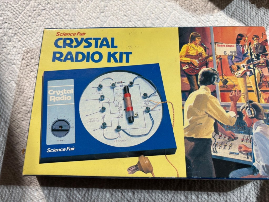
My first radio project was a crystal radio which was similar to the above picture. As a poor student, the selling price of the kit was too much for me. Fortunately I found a article on building crystal radios from an electronics magazine. I copied the circuit, bought low cost components from the surplus market, and built it. To my delight, it worked as soon as I completed the soldering.
Sensitivity was poor. Only a couple of strong local stations could be received and the volume was very low, just barely audible, but the excitement was very high. I wanted to build more complex radios that had higher performance in no time!
Tips for experimenters
While the circuit of a typical crystal radio is extremely simple, there are few key points to observe in order to have satisfactory result. Refer to fig.1 for the following discussion.
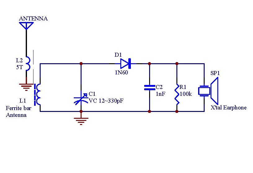
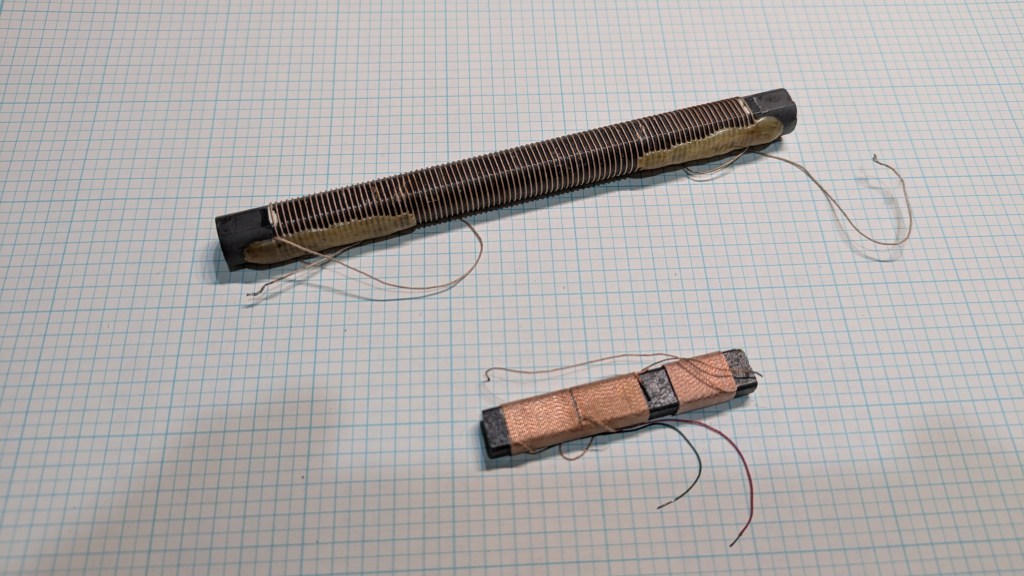
- L1 should be a ferrite-rod coil which also serves the purpose of an antenna. The larger (longer) the ferrite rod, the better. (See fig.2.) Some builders recommend using big air coil instead of ferrite-rod coil. In that case, an long-wire antenna (and L2) must be added. My experience is that the ferrite-rod gives better result.
- L2 is 5~10 turns of AWG30 enameled copper wire wound around the ferrite bar, next to the “main coil” L1. The antenna is a long wire of 5m or more. You may not need L2 and the long-wire antenna if your local stations are strong enough.
- C1 is a variable capacitor which capacitance must match the inductance of L1 in order to receive the desired frequency band, in our case, the standard AM broadcast band: 530~1700 kHz. Some component stores sell a combo of ferrite-rod coil with a VC that can tune to the entire AM broadcast band.
- D1 should be a germanium diode for best result. Unfortunately Ge diodes are hard to find nowadays. The best compromise is a small-signal Schottky diode; silicon diodes like 1N4148 are no good. (I will write a post to explain why the diode matters.)
- SP1 is a crystal earphone (see the photo at the top) which is highly sensitive. It also has high impedance so that the LC tuned circuit will not be loaded down, and hence sensitivity suffers. Some articles suggest using high-Z moving-coil earphone (Z = 2 kOhm, typical) which is (much) inferior to a crystal earphone.
What’s next?
The coolest thing of a crystal radio is that it needs no power to work. However it is usable only in locations relatively close to radio transmitting stations. In pursue of better performance, my next project was a 2-transistor reflex radio.


 From Hobby to Professional
Leave a comment